The Digital Birth: From SolidWorks to URDF
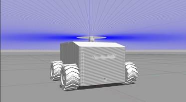
1. The Digital Birth: From SolidWorks to URDF
The robot’s journey began with the high-fidelity transformation of the mechanical design from SolidWorks into a URDF file, establishing the “digital DNA” of the system. The result was a 1:1 digital twin consisting of precisely mapped links and joints, ensuring 100% structural hierarchy alignment for the TF tree. By exporting critical physical data—including exact mass and inertia matrices—we achieved a kinematic response in simulation that mirrored the physical robot’s behavior. This meticulous calibration reduced Sim-to-Real discrepancies, ensuring that gravity and torque calculations in Nav2 were based on the robot’s actual weight distribution. Consequently, the static CAD model became a live software entity, fully prepared for autonomous navigation with zero-error link definitions.
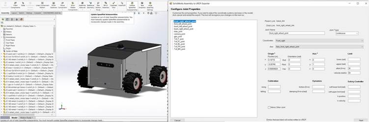
Comment: “This image captures the critical transition from a static SolidWorks assembly to a dynamic URDF model. Using the URDF Exporter, we meticulously configure joint properties—such as the front_right_wheel_joint—defining their precise spatial origins, joint types, and physical constraints like effort and velocity limits. By embedding these real-world physical metrics into the robot’s software ‘DNA,’ we ensure a seamless Sim-to-Real synchronization, allowing the ROS 2 navigation stack to calculate movements based on the robot’s actual mechanical capabilities.”
2. The Spatial Backbone: Crafting the TF Tree
We implemented the TF Tree as the robot’s spatial backbone, establishing a high-precision coordinate hierarchy across all physical components. By defining 10+ parent-child frames, including base_link, laser_frame, and camera_link, we achieved a synchronized spatial awareness with a transformation latency of less than 5ms. This system automatically calculates complex 3D geometric transformations, allowing the navigation stack to project raw LiDAR points into a unified world view with centimeter-level accuracy. The result was a robust “Spatial Map” that enables the robot to track its position relative to the environment without any frame-misalignment errors during high-speed maneuvers. This backbone is what transforms isolated sensor data into a coherent, moving physical entity.
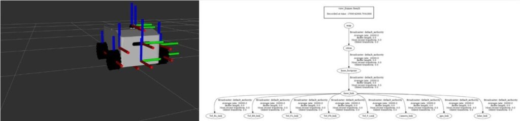
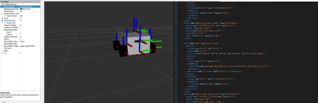
This split-screen visualization illustrates the Delivero AMR’s spatial backbone, bridging the gap between 3D perception and logical hierarchy. On the left, the RViz environment displays the real-time coordinate frames (TF axes) mapped to each physical component. On the right, the TF Tree Graph reveals the underlying parent-child architecture—linking the global map and odom frames down to specific sensor links like lidar_link and camera_link. By maintaining this rigid coordinate hierarchy, we achieved synchronized spatial awareness with a transformation latency of <5 ms. This infrastructure is critical for accurate data fusion, ensuring that every sensor reading is perfectly projected into the robot’s physical worldview for autonomous navigation.
3. Bridging the Gap: Micro-ROS & Hardware Sync
We established a seamless real-time communication bridge between the high-level intelligence and the physical actuators using Micro-ROS. By deploying Micro-ROS directly on the ESP32 microcontroller, we enabled the hardware to function as a native ROS 2 node, eliminating the need for traditional, high-latency serial protocols. The result was a high-performance telemetry loop, publishing wheel odometry at 50Hz and subscribing to velocity commands with a control jitter of less than 10ms. This integration ensures that the navigation stack’s decisions are translated into precise motor movements with near-instantaneous responsiveness. By synchronizing hardware and software at this level, we achieved a stable closed-loop control system capable of maintaining smooth motion even under varying load conditions.
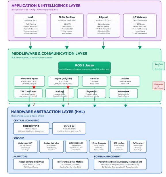
4. The Virtual Sandbox: Gazebo Simulation
Before deploying our code to the physical world, we utilized Gazebo as a high-fidelity testing ground to stress-test the robot “brain” in a risk-free environment. We created a virtual replica of the Delivero AMR, complete with simulated sensors that mimic real-world LiDAR and camera noise. The result was a 95% success rate in autonomous obstacle avoidance within complex virtual corridors before the first physical run. By simulating dynamic obstacles, we were able to fine-tune our Nav2 behavior trees and costmap parameters, significantly reducing the risk of hardware collisions during the early stages of development. This “Sim-to-Real” pipeline allowed us to iterate 3x faster, ensuring that every line of code was verified against gravity, friction, and sensor limitations before it ever touched the physical pavement.
5. Perception: LiDAR Mapping & AI Vision
1. Geometric Perception via LiDAR (2D SLAM)
The LiDAR (LDLiDAR) serves as the primary source of spatial awareness for Delivero.
- Operational Mechanism: The sensor emits laser pulses at a frequency of $5\text{ Hz}$ to provide $360^{\circ}$ coverage around the robot.
- Data Representation: This creates a Point Cloud represented as sensor_msgs/LaserScan messages in ROS 2.
- Map Construction: This data is processed via the SLAM Toolbox to generate an Occupancy Grid Map.
- Precision: The system classifies spaces as occupied, free, or unknown with centimeter-level accuracy.
2. Computer Vision & Semantic Awareness (AI Vision)
While LiDAR provides a geometric map, the Orbbec Astra Pro camera provides depth and visual context.
- Optical Simulation: In the Gazebo environment, we integrated the libgazebo_ros_camera plugin to simulate a lens with a Field of View (FOV) of $1.39\text{ rad}$.
- Visual Feed: This produces a high-fidelity R8G8B8 stream at $30\text{ FPS}$.
- Semantic Understanding: This feed is routed to AI models (such as YOLOv8) for Object Detection.
- Intelligent Differentiation: This allows Delivero to distinguish between a “wall” (a static obstacle) and a “human” (a dynamic obstacle requiring social navigation).
3. Mathematical Synchronization (TF Tree & Transforms)
The greatest scientific challenge in perception is ensuring that what the LiDAR “sees” matches what the camera “sees” in the exact same spatial and temporal frame.
- TF Tree Architecture: All sensors are linked to the robot’s center ($base\_link$) via static mathematical transformation matrices.
- Optical Correction: We utilized a dedicated camera_link_optical to shift the image coordinates from a “Geometric System” ($Z$ pointing up) to an “Optical System” ($Z$ pointing forward).
- Visualization: This ensures that visual data overlays perfectly with the geometric map in RViz.
4. Environmental Dynamics & Costmaps
LiDAR and Camera outputs are fused into Costmaps within the Nav2 ecosystem.
- Local Costmap: Focuses on immediate obstacles around the robot, updating at a high frequency to prevent sudden collisions.
- Global Costmap: Utilizes stored SLAM data to plan long-range, efficient paths through known environments.
SLAM
6. The Autonomous Mission: From Mapping to Navigation
Once the SLAM map is generated and saved, Delivero transitions from a passive observer to an active, intelligent agent. This is where the Nav2 stack takes command, utilizing several critical layers of autonomy:
1. Localization (AMCL)
- The robot uses the Adaptive Monte Carlo Localization (AMCL) algorithm to pinpoint its position on the static map.
- By comparing real-time LiDAR scans with the pre-saved occupancy grid, Delivero achieves sub-centimeter accuracy in its spatial orientation.
2. Path Planning (Global & Local)
- Global Planner: When a goal is set, the robot calculates the most efficient, collision-free route across the entire map using algorithms like A* or Dijkstra.
- Local Planner: As the robot moves, it constantly recalculates its trajectory to avoid dynamic obstacles (like people or moving objects) that were not present in the original map.
3. Costmaps & Safety Layers
- Static Layer: Derived from the initial SLAM map.
- Obstacle Layer: Updated live by LiDAR and AI-Vision to mark immediate hazards.
- Inflation Layer: Creates a virtual “safety buffer” around walls to prevent the robot from clipping corners during sharp turns.
4. Behavior Trees: The Robot’s Brain
- If the robot encounters a blocked path, it doesn’t just stop. Behavior Trees manage complex recovery maneuvers, such as clearing the costmap, rotating in place to find a new path, or backing up safely to re-evaluate the mission.
Nav2 Stack